Connecting room computers and guest laptops
You can connect room computers and guest laptops to the display and view and interact with them.
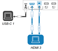
- USB-C 1
- USB-C 2
- HDMI 1
- HDMI 2
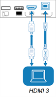
- HDMI 3
- HDMI 4
- VGA


Connector | Standard | Connection type |
|---|---|---|
USB-C 1 | USB 3.2 Gen 1×1 (as DFP) Display Port 1.2.4-lane (as UFP) | Video/audio/touch/network |

Connector | Standard | Connection type |
|---|---|---|
USB-C 2 | USB 3.2 Gen 1×1 (as DFP) Display Port 1.2.4-lane (as UFP) | Video/audio/touch/network |

Connector | Standard | Connection type |
|---|---|---|
HDMI 4 | HDMI 2.1 | Video/audio |
Touch (USB Type-B) | USB 3.2 Gen 1 | Touch |
Note
The HDMI 4 and VGA inputs share a USB Type-B receptacle.

Connector | Standard | Connection type |
|---|---|---|
VGA | Video | |
Audio In (Stereo 3.5 mm) | Stereo 3.5 mm | Audio |
Touch (USB Type-B) | USB 3.2 Gen 1 | Touch |
Note
The HDMI 4 and VGA inputs share a USB Type-B receptacle.
Side and bottom connector panels
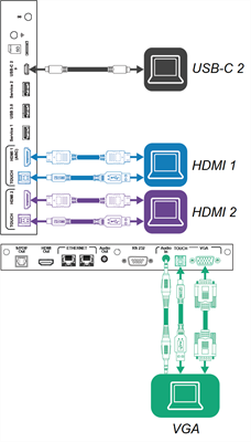
Front connector panel
Note
Not all SMART Board MX (V4) series models include connectors for the VGA input.
Side and bottom connector panels
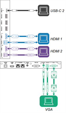
Front connector panel
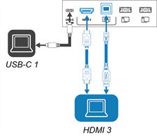
SMART Board MX (V2-C) series
Side and bottom connector panels
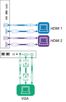
Front connector panel
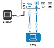
SMART Board MX (V2) Pro series
Side and bottom connector panels

Front connector panel
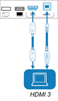
Side and bottom connector panels
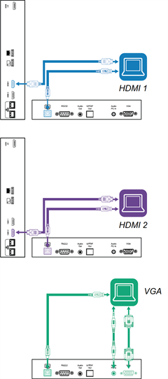
Front connector panel
Warning
Ensure that any cables that cross the floor to the display are properly bundled and marked to avoid a trip hazard.
Caution
When connecting a USB cable to a computer, make sure the computer has a USB compliant interface and bears the USB logo. In addition, the USB source computer must be compliant with IEC 62368‑1. The source computer must be CE marked and carry safety certification marks for Canada and USA. This is for operating safety and to avoid damage to the display.
Notes
A room computer or guest laptop connected to the display through a USB Type-B or Type-C receptacle has access to any networks connected to the display by Ethernet while the computer is the currently selected input on the display.
Install SMART software on any computers you connect to the display.
Your organization’s installers might have connected cables to the display and run the cables behind a wall or under the floor to a desk or table where you can place your computer.
If a connected computer reports “Too many USB hubs” or “cannot start (code 10),” see the knowledge base article, SMART Board interactive displays and USB tier structure use.
Connect the computer to the display.
View the available inputs in one of the following ways:
If the display has iQ, tap Input
 on the Home screen.
OR
If the display doesn’t have iQ, press the Home button
 .
.Press Input
on the front control panel.
Press Input
on the remote control.
The input selection menu appears.
Tap the computer’s input menu option.
Connect the computer to the display.
View the available inputs in one of the following ways:
If iQ is enabled, tap Input
 on the Home screen.
OR
If iQ is disabled, press the Home button
 .
.If iQ is disabled, press the Home button
on the front control panel.
Press Input
on the front control panel.
Press Input
on the remote control.
The display shows thumbnails of the devices that are connected to the display’s inputs:
A gray thumbnail indicates no device is connected to an input.
A black thumbnail indicates a device is connected to an input but is in Standby mode.
A thumbnail showing a preview screen indicates an active device is connected to an input.
A thumbnail with Touch enabled
 indicates a USB cable is connected between the display and device and touch control is available.
Tap the computer’s thumbnail.
Connect the computer to the display.
Press Input
on the front control panel.
The input selection menu appears.
Note
Inputs with connected devices are blue, and inputs without a connection are black.
Tap the computer’s input menu option.
This table presents the recommended resolutions and refresh rates for the display’s USB-C and HDMI inputs:
This table presents the recommended resolutions and refresh rates for the display’s HDMI inputs:
Resolution | Input aspect ratio | Mode | Refresh rate |
|---|---|---|---|
3840 × 2160 | 16:9 | UHD/2160p | 59.94 Hz/60 Hz 50 Hz 29.97 Hz/30 Hz 25 Hz 23.98 Hz/24 Hz |
1920 × 1080 | 16:9 | FHD/1080p | 59.94 Hz/60 Hz 50 Hz 29.97 Hz/30 Hz 25 Hz 23.98 Hz/24 Hz |
1360 × 768 | 16:9 | HD | 60.015 Hz |
1366 × 768 | 16:9 | HD | 60.015 Hz |
1280 × 720 | 16:9 | HD/720p | 59.94 Hz/60 Hz 50 Hz 29.97 Hz/30 Hz 25 Hz 23.98 Hz/24 Hz |
720 × 480 | 16:9 | 480p (DVD Player) | 60 Hz |
This table presents the recommend resolutions and refresh rates for the display’s VGA input:
Resolution | Input aspect ratio | Mode | Refresh rate |
|---|---|---|---|
1920 × 1080 | 16:9 | N/A | 60.000 Hz |
1600 × 1200 | 4:3 | N/A | 60.000 Hz |
1360 × 768 | 16:9 | N/A | 60.015 Hz |
1280 × 1024 | 5:4 | SXGA 60 | 60.020 Hz |
1024 × 768 | 4:3 | XGA 60 XGA 70 XGA 75 | 60.004 Hz 70.069 Hz 75.029 Hz |
800 × 600 | 4:3 | SVGA 60 SVGA 72 SVGA 75 | 60.317 Hz 72.188 Hz 75.000 Hz |
640 × 480 | 4:3 | VGA 60 | 59.940 Hz |
If possible, set connected computers to these resolutions and refresh rates. See the connected computers’ operating system documentation for instructions.
You can use USB drives, peripherals, and other devices with a computer connected to the display using the USB receptacles on the display.
- SMART Board MX (V5) and MX (V5) Pro series installation and maintenance guide – 171897
- SMART Board MX (V4) and MX (V4) Pro series installation and maintenance guide – 171870
- SMART Board MX (V3) and MX (V3) Pro series installation and maintenance guide – 171895
- SMART Board MX (V2 and V2-C) and MX (V2 and V2-C) Pro series installation and maintenance guide – 171555
- SMART Board MX and MX Pro series installation and maintenance guide – 171257


