Getting started
Once you install the SMART Board interactive whiteboard and software and complete the calibration and orientation, you can use the interactive whiteboard to write, erase and move objects, open applications, use Ink Aware programs and save your notes on the computer.
How you turn on the interactive whiteboard, computer, and projector depends on how the interactive whiteboard is configured:
If a basic power control module is attached to the left side of the pen tray (because the interactive whiteboard is not part of a projector system), turn on the computer, turn on the projector, and then press the Power button on the basic power control module to turn on the interactive whiteboard.
If an Extended Control Panel (ECP) is attached to the left side of the pen tray (because the interactive whiteboard is part of a projector system), turn on the computer and then press the Power button on the ECP to turn on the projector and the interactive whiteboard.
If an Appliance Control Panel (ACP) is attached to the left side of the pen tray (because the interactive whiteboard is part of a projector system with an appliance), turn on the computer and then press the Power button on the ECP to turn on the projector, the interactive whiteboard, and the appliance.
Each time you turn on the interactive whiteboard, the pen color buttons cycle twice, and then the light comes on only for the ink color you select.
When your computer is on and the Power button is off, the interactive whiteboard is in Standby mode. Press the Power button to wake up the interactive whiteboard. When you finish, press the Power button again to return it to Standby mode.
The left side of the pen tray has Power, Orientation and Help buttons, as well as the Ready light.

Note
The above diagram shows the basic power module:
For information on the additional features of the Extended Control Panel (ECP), see Using the Extended Control Panel (ECP).
For information on the additional features of the Application Control Panel (ACP), see Using the Application Control Module (ACM)
Component | Description |
|---|---|
Power button | Press this button to put your interactive whiteboard into Standby mode when it isn’t in use, or to restore full power to it when you need to use it. Ensure that the interactive whiteboard is connected to your computer and to a wall power outlet. |
Orientation button | Press this button to start the orientation process. Orienting your interactive whiteboard ensures that the mouse pointer or digital ink appears directly below your finger or pen tray tool when you touch the interactive surface. Refer to Orienting the interactive whiteboard for information on performing an orientation procedure. |
Help button | Press this button to access on-screen Help options, including links to online Help files, troubleshooting options and contact information for SMART Support. |
Ready light | This light indicates the status of the interactive whiteboard’s controller module. The Ready light is solid green when the system is working properly. |
The following table shows the Ready light’s normal states.
Ready light state | Description |
|---|---|
Solid red | Your interactive whiteboard is receiving power from the power cable, but isn’t communicating with a computer. |
Flashing green | Your interactive whiteboard is receiving power and is communicating successfully with your computer’s USB HID driver. SMART Product Drivers isn’t installed. Note In HID mode, interactive whiteboard tools such as the pens and the eraser don’t work, but you can move the mouse pointer and perform mouse functions by touching the interactive surface. The Right-click button on the pen tray might work, depending on the version of operating system you’re using. Neither the Keyboard nor the Help button work in HID mode. |
Solid green | Your interactive whiteboard is receiving power and is communicating successfully with SMART Product Drivers. |
Flashing amber | The controller module is in a service mode or the firmware is being updated. |
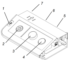
If your interactive whiteboard is bundled with a SMART or Epson for SMART projector as part of a projector system, the Extended Control Panel (ECP) attaches to the left side of the interactive whiteboard pen tray. The ECP gives you control of the interactive whiteboard’s basic operations. Press the Power button on the ECP to put the projector into Standby mode or to turn it on. Press the ECP’s Input button to switch sources on the projector.
Important
Do not disconnect cables from the ECP to connect peripheral devices because you could disconnect controls for the interactive whiteboard.
The following diagram and table describe the components of the ECP.

Number | Function |
|---|---|
Left side | |
1 | USB A receptacle (for USB drives) Note USB drives that you connect to this receptacle are accessible only to the room computer (the computer connected to the USB1 receptacle). |
Front | |
2 | Interactive whiteboard and projector Power |
3 | Projector volume control |
4 | Projector input selection |
Back | |
5 | Two mini USB B receptacles (connect to room computer and laptop) |
6 | 11-pin connector (connects to projector integration cable harness) |
7 | 4-pin connector (for optional room control) |
Note
Use an 800 series control cable (Part No. SBX8-CTRL) to convert the 4-pin connector to a DB9F RS‑232 connector for use with a third-party room control system. You can purchase an SBX8 series control cable from your local SMART reseller.
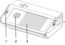
If your interactive whiteboard is bundled with a SMART projector and appliance as part of a projector system, the Application Control Panel (ACP) attaches to the left side of the interactive whiteboard pen tray. The ACP gives you control of the basic operations of your interactive whiteboard system. Press the Power button on the ACP to start the interactive whiteboard system. The button flashes green until the interactive whiteboard system is on. Use the LCD touch screen on the ACP to turn the interactive whiteboard system off and on, control volume, switch inputs and applications, control projector and LCD settings, and access system and status information. You can also set your system to low power mode by selecting Turn Off on the LCD touch screen.
Important
Do not disconnect cables from the ACP to connect peripheral devices because you could disconnect controls for the interactive whiteboard.
Note
Low power mode reduces the power consumption of your interactive whiteboard system when it’s in Shutdown mode.
To set the projector system to Low power mode, access the low power mode options through the LCD touch screen’s system settings.
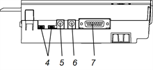
The following diagrams and table describe the components of the ACP.


Number | Function |
|---|---|
1 | USB A receptacle (for USB drives) |
2 | Power |
3 | LCD touch screen |
4 | Mini USB B receptacles (x2) (connect to appliance and laptop) |
5 | 2.0 mm male barrel connector to appliance (DC-out) |
6 | 2.5 mm male barrel connector to power supply (DC-in) |
7 | 15-pin connector (connects to ACP harness cable) |