Connecting power, cables and devices
Connect the display to power after you install it but before you turn it on for the first time. You can also connect cables for room computers, guest laptops or other input sources as well as for speakers and room control systems.
By installing cables in advance, you make use of connectors that might not be accessible after the display is wall-mounted. You can then run the cables across floors or behind walls as needed.
Warning
Ensure that any cables that cross the floor to the display are properly bundled and marked to avoid a trip hazard.
SBID-MX165

SBID-MX175

SBID-MX186

Connect the supplied power cable from the AC power inlet on the side of the display to a power outlet.
Note
Refer to the display’s specifications for power requirements and power consumption information (see Specifications).

The SMART Board MX100 series interactive displays require a network connection for downloading software and firmware updates. You can connect to a network using one of the RJ45 jacks on the display (pictured) or using a Wi-Fi connection. For more information about the display’s network connection and configuration, see Connecting to a network.
You can also connect a computer to the display’s other RJ45 jack so the display and computer are connected to the same network.
You can connect cables to the display so that users can connect and use room computers, guest laptops or other devices, such as Blu-ray disc players.
Notes
If your display is configured with firmware 2.0.6 (and later), you can configure the HDMI version for each HDMI connector as either HDMI 1.4 or HDMI 2.0. This allows you to connect HDMI 1.4 devices that are incompatible with HDMI 2.0 connectors and would otherwise appear as DVI devices, see HDMI [connector number]-EDID version.
For information about configuring connected computers, see Connecting and using computers.
SMART recommends the following varieties of cable:
Cable type | Maximum length | Recommendation |
|---|---|---|
HDMI | 23' (7 m) 1 | Use only certified HDMI cables that have been tested to support the performance standard you require. See HDMI cables and connectors for more information. |
VGA | 23' (7 m) | Use VGA cables with all pins in their connectors fully populated and wired. See VGA cables and connectors for more information. |
Stereo 3.5 mm | 20' (6 m) | [N/A] |
USB | 16' (5 m) | Use a USB extender if the distance between the computer and the display is greater than 16' (5 m). For more information, see USB extenders. For more information about USB cables, see USB cables and connectors. |
Using cables that exceed these maximum lengths may produce unexpected results, such as degraded picture quality or degraded USB connectivity.
 |  |
The side connector panel includes two HDMI video connectors: HDMI 1 and HDMI 2. Both connectors can accommodate an HDMI cable for video and audio, and both support HDMI 2.0.
Notes
The USB Type-B connector for touch control is located on the bottom connector panel. See Connecting to the bottom connector panel.
You can connect a wireless USB keyboard and mouse to the two USB Type-A connectors.

The bottom connector panel includes a video connector and USB connector:
VGA: This connector can accommodate a VGA cable for video.
USB Type-B: This connector can accommodate a USB cable for touch control for computers connected to HDMI 1, HDMI 2 or VGA.
Note
When connecting a computer to the VGA connector, use the Stereo 3.5 mm in connector for audio.

In addition to the three sets of video connectors on the side and bottom connector panel, there is one set of computer connectors on the front control panel:
HDMI 3: This set of connectors can accommodate a USB cable for touch control and an HDMI cable for video and audio. This input supports HDMI 1.4 with HDCP 1.4.
USB Type-B: This connector can accommodate a USB cable for touch control for computers connected to HDMI 3.
Users can use the Input app or tap the Input button to open the input selection menu. Tap an input source to view the computer or other device’s input on the display. See Using Input.
The display includes two 10 W speakers, which are designed to provide sound at the front of a room. You can connect external active speakers if you’re providing sound in a larger space. See SMART Audio 400 classroom amplification system for more information.

You can connect external speakers to the display using the stereo 3.5 mm out connector (pictured).

The display also provides a Sony/Philips Digital Interface (S/PDIF) optical out connector. S/PDIF is a digital audio transmission medium. You need an audio receiver that supports S/PDIF to decode this connection to analog for use with external speakers.
A room control system enables users to control a room’s lighting, audio system and, possibly, the display. Some installations may require you to integrate the display with a room control system.
You can use the display’s RS-232 connector to connect a third-party external control system to the display (see Remotely managing your display using RS-232).
Note
Displays are not compatible with centralized remote control systems, such as a universal remote control.
The following diagram and table present the connectors on the display’s connector panel:

No. | Connector | Connects to | Notes |
|---|---|---|---|
1 | HDMI 1.4 out (HDCP-compliant) | External monitor | This connector is HDCP-encrypted HDMI. Note HDMI out is an optional feature. Contact your authorized SMART reseller (smarttech.com/where) for further ordering instructions. |
2 | USB 2.0 Type-A connector | USB drives and other devices | Connect a USB drive and other devices that you want to use with the e³ experience. Note If troubleshooting an issue with the display, connect a USB mouse to navigate the display’s on-screen menu. |
3 | USB 2.0 Type-A connector | USB drives and other devices | Connect USB drives and other devices that you want to use with the currently selected input source. |
4 | HDMI 1 2.0 in | HDMI 1 input (video and audio) | See Connecting cables for room computers, guest laptops and other input sources. |
5 | HDMI 2 2.0 in | HDMI 2 input (video and audio) | See Connecting cables for room computers, guest laptops and other input sources. |
6 | RJ45 (×2) | Network |
The following diagram and table present the connectors on the display’s bottom connector panel:
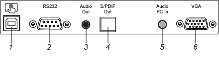
No. | Connector | Connects to | Notes |
|---|---|---|---|
1 | USB 2.0 Type-B | HDMI 1, HDMI 2 or VGA input (touch) | See Connecting cables for room computers, guest laptops and other input sources. |
2 | RS-232 | Room control system | |
3 | Stereo 3.5 mm out | External speakers or audio system | |
4 | S/PDIF out | Optical digital audio output | |
5 | Stereo 3.5 mm in | VGA input (audio) | See Connecting cables for room computers, guest laptops and other input sources. |
6 | VGA in | VGA input (video) | See Connecting cables for room computers, guest laptops and other input sources. |
The following diagram and table present the connectors on the display’s front connector panel:
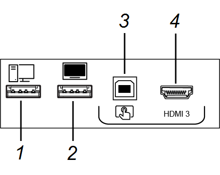
No. | Name | Procedure |
|---|---|---|
1 | USB 2.0 Type-A connector | Connect USB drives and other devices that you want to use with the currently selected input source. |
2 | USB 2.0 Type-A connector | Connect a USB drive and other devices that you want to use with the e³ experience. |
3 | USB 2.0 Type-B connector | Connect a USB cable to the display and computer to provide touch control of the computer connected to HDMI 3. |
4 | HDMI 3 input connector | Connect a computer or other input source to the display (see Using Input). |
There are additional connectors on the bottom of the display (see Installing the display on a wall and Remotely managing your display using RS-232).