Downloading, installing, and running FRU software
After you’ve replaced a camera or the DSP controller in a SMART Board M600 series interactive whiteboard, download and run the FRU software that’s compatible with the DSP controller’s firmware version.
Before you download and run the FRU software, locate the interactive whiteboard’s serial number and identify which version of the FRU software you need to download.
To locate the interactive whiteboard’s serial number
Look for a serial number label on the bottom-right edge of the interactive whiteboard’s frame or on the back of the interactive whiteboard.
To identify which version of FRU software to download
On a computer connected to the interactive whiteboard, open SMART Settings.
Tap SMART Hardware Settings.
If the computer is connected to more than one SMART product, tap the link for the interactive whiteboard.
Select Hardware Info & Settings in the drop-down list.
Hardware information and settings appear. This information includes the DSP controller firmware version.
Identify which version of the FRU software you need to download for the DSP controller firmware version:
DSP controller firmware version
FRU software version
7.2.48
2.4.17.0 (September 2019)
7.2.40
2.4.15.0 (August 2017)
7.2.31
2.4.10.0 (June 2014)
7.2.28
2.2.44.3 (February 2014)
Tip
If the DSP controller firmware version is older than those listed above, upgrade it using the SMART Firmware Updater that is part of SMART Product Drivers.
Download and install the FRU software on a computer running Windows 7 SP1 or later operating system with Region and Language settings set to an English language locale. The FRU software is designed to run on only English language Windows operating systems.
Tip
If your computer’s Region and Language settings are not set to an English language locale, you can change them to an English language locale temporarily to install and run the FRU software.
To download and install the FRU software
Go to FRU software.
Click one of the following buttons:
ZIP file – Version 2.4.17.0 – Firmware 7.2.48
ZIP file – Version 2.4.15.0 – Firmware 7.2.40
ZIP file – Version 2.4.10.0 – Firmware 7.2.31
ZIP file – Version 2.2.44.3 – Firmware 7.2.28
Save the .zip file to a temporary location on the computer.
Extract the .exe file from the .zip file to a temporary location on the computer.
Double-click the .exe file and follow the on-screen instructions to install the FRU software.
After you’ve downloaded and installed the FRU software, you can run it.
Important
Before running the FRU software, make sure the projected image is aligned and fills the entire projection surface area of the interactive whiteboard. If the projected image is not aligned or does not fill the entire projection surface area, you might not be able to complete the calibration process.
To run the FRU software
If the FRU software isn’t already running, double-click SBR_CUSTOMER_FRU AutoStart on the desktop.
The Start screen appears.
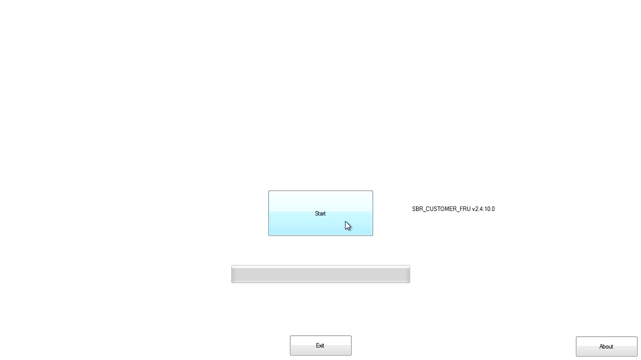
Tap Start.
If you replaced the DSP controller, type the interactive whiteboard’s serial number in the Scan SMART Barcode box, and then tap Continue:
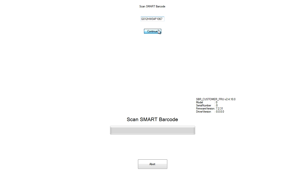
Important
If you replaced the DSP controller but the Scan SMART Barcode box does not appear, restart the interactive whiteboard with the computer still connected. This should resolve the problem, and the Scan SMART Barcode box should appear.
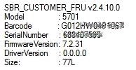
The FRU software sets parameters for the interactive whiteboard’s model and size. The following information appears on screen:
CopySet VidPidModel
Stop Windows Service
Restart DSP
Load DefaultsMake sure the serial number that appears in the bottom-right of the screen (along with the internal model number, firmware version and interactive whiteboard size) matches the interactive whiteboard’s serial number.
Important
If the on-screen serial number does not match the interactive whiteboard’s serial number, the DSP controller may have been previously configured for another interactive whiteboard. Close the FRU software and replace the DSP controller with a new one that has not been configured with another interactive whiteboard.
Note
If you’re not running the correct version of the FRU software for the DSP controller firmware version, an error message appears. Close the FRU software and download, install and run the correct version of the FRU software for the DSP controller firmware version.
Monitor the FRU software as it progresses through the following stages:
Stage
Description
If errors occur
Check Scopes
Checks that the all the cameras are connected and in the correct positions
Access the camera scopes view window by pressing SHIFT+CTRL. (For information on how to read the data in this window, see Understanding SMART Board M600 series interactive whiteboard sensor data.)
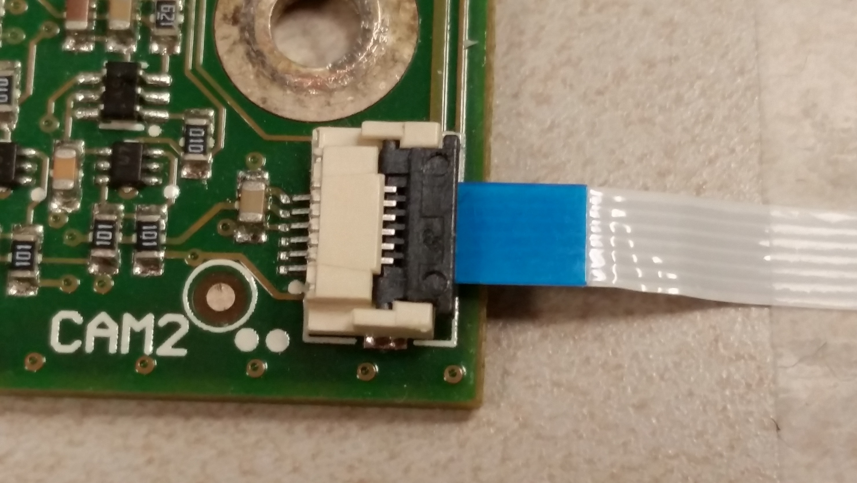
If a camera doesn’t show a signal or show a saturated (maxed-out) signal, confirm that the flexible cable (FFC) connections between the camera and the DSP controller are properly attached, inserted correctly and not at an angle.
Pixel Map
Checks that the cameras are looking at the retro-reflective bezels correctly
Access the camera scopes view window by pressing SHIFT+CTRL. (For information on how to read the data in this window, see Understanding SMART Board M600 series interactive whiteboard sensor data.)
If a camera doesn’t show a signal, make sure the FFC connections between the camera and the DSP controller are not damaged and are properly attached.
Make sure all the camera scopes are complete. If they aren’t, make sure all the retro-reflective tape on the bezel is clean, undamaged and unobstructed.
If a camera’s scope is misaligned, make sure that camera is securely screwed flat on the interactive whiteboard surface and that the interactive whiteboard surface is also flat and undamaged.
Led Aperture
Checks that the cameras have the correct field of view
Access the camera scopes view window by pressing SHIFT+CTRL. (For information on how to read the data in this window, see Understanding SMART Board M600 series interactive whiteboard sensor data.)
If a cameras doesn’t show any signal, confirm that the FFC connections between the camera and the DSP controller are not damaged and are properly attached.
If a camera’s scope is misaligned, make sure that camera is securely screwed flat on the whiteboard surface and not rotated, and that the interactive whiteboard surface is also flat and undamged.
AutoCam
Adjusts the exposure time for each camera
Access the camera scopes view window by pressing SHIFT+CTRL. (For information on how to read the data in this window, see Understanding SMART Board M600 series interactive whiteboard sensor data.)
If a camera doesn’t show any signal, confirm that the FFC connections between the camera and the DSP controller are not damaged and are properly attached.
Make sure all the camera scopes are complete, without any anomalies. If the scopes are not complete or show abnormal drops or spikes in the level of reflected IR light, make sure all the retro-reflective tape on the bezel is clean, undamaged and unobstructed.
On the right side, if a camera shutter value is displayed as 3999, make sure the camera lenses are clean. Do not touch the lenses or use isopropyl alcohol. Only use a bellows bulb (a common camera cleaning tool, available at any camera store) to gently remove any dust, without actually touching the lens.
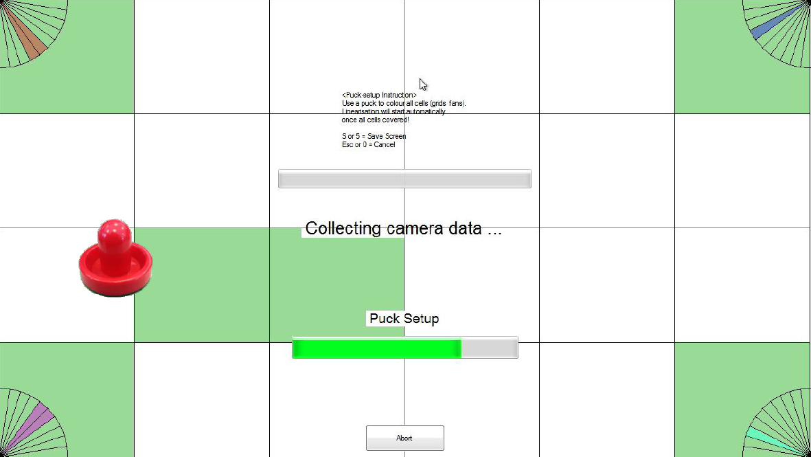
Drag the calibration puck (included with the FRU part) through all of the squares on the Puck Setup screen.
Note
If the calibration puck is not available, you may be able to use any similar circular object with a similar diameter (94 mm), as long as it is not transparent or highly reflective, and will not scratch the interactive whiteboard’s surface. A table-hockey puck, or a foam-bottom coffee mug are examples of alternative tools.
Important
Make sure the projected image is aligned and fills the entire projection surface area of the interactive whiteboard. If the projected image is not aligned or does not fill the entire projection surface area, you might not be able to complete the calibration process on the Puck Setup screen.
Make sure your fingers remain inside the calibration puck at all times and that no other objects come near the interactive whiteboard’s surface.
As the puck passes through each square, the square changes from white to green. At the same time, the fans in the corners indicate the optical viewing angles through which each camera detects the calibration puck.
If a square other than the one you’re passing the puck through turns green, some cameras may not be connected to the correct ports on the DSP controller. You need to correct this and run the FRU software again.
Notes
You can access the camera scopes view window by pressing SHIFT+CTRL. (For information on how to read the data in this window, see Understanding SMART Board M600 series interactive whiteboard sensor data.)
Place a large object (such as the calibration puck) in each corner of the screen while looking at the camera scope views to determine which cameras are not connected to the correct ports on the DSP controller.
Camera scope view color
Camera scope view label
Physical port on the DSP controller
Physical location on the interactive whiteboard
Red
Cam:0
CAM1
Top-left
Blue
Cam:1
CAM2
Top-right
Brown
Cam:2
CAM3
Bottom-right
Green
Cam:3
CAM4
Bottom-left
If all slices in the corner fans don’t change color after you’ve passed the calibration puck through all the squares, move the calibration puck into an area of the screen that the non-colored slices point to.
Example
The bottom-right slice in the top-right fan hasn’t changed color, indicating an issue with the right edge of the screen:

Move the puck closer to the right edge of the screen to address the issue.
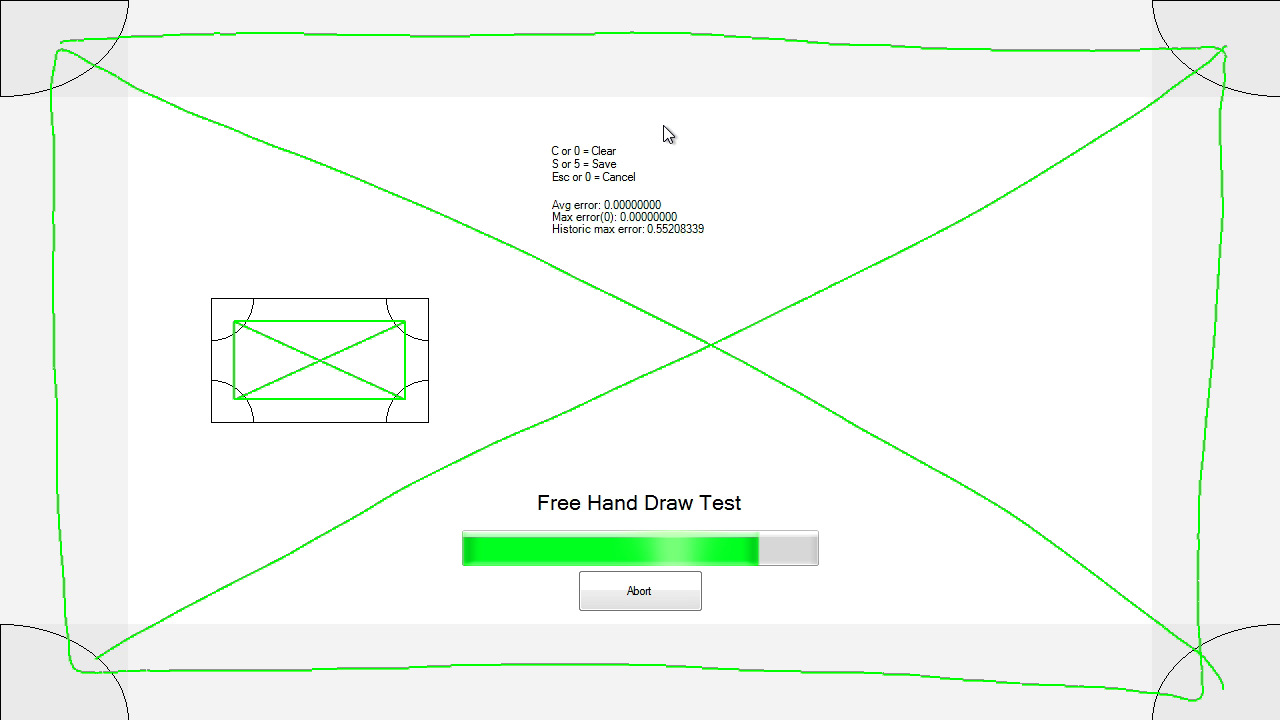
Using the interactive whiteboard’s pen, draw lines from each corner to each other corner on the Free Hand Draw Test screen:
Important
Make sure the pen’s tip contacts the interactive whiteoboard’s surface at a right angle and that no other objects come near the interactive whiteboard’s surface.
The FRU software finishes setting the parameters for the interactive whiteboard. The following information appears on screen:
Copyfinalise-reworkDate
finalise-commit
finalise-commitDefaults
finalise-checksum
finalise-capturescopes
settings.final.xmlTap PASS, and then tap Exit.

Tap the SMART Board icon
 in the notification area, and then select Orient.
Orient the interactive whiteboard’s touch system to the computer’s display (see Orienting your SMART interactive product).