Using the receiver
The receiver for the SMART Audio 400 classroom amplification system receives an audio signal and transmits it to the speakers. Pairing the microphones and the receiver is easy, and the receiver doesn’t allow unpaired microphone audio to bleed into the speaker system. The LEDs make it easy to tell at a glance if microphones are properly connected.
 About the receiver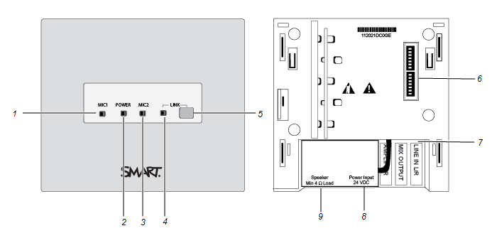
No. | Function | Description |
|---|---|---|
1 | MIC1 | LED indicates that a microphone is paired. |
2 | POWER | LED indicates the power status. |
3 | MIC2 | LED indicates that another microphone is paired. |
4 | LINK | LED indicates the pairing status. |
5 | Link button | Press the Link button to pair the receiver with the microphones. See Pairing the microphones for more information. |
6 | Dip switches | See Troubleshooting SMART Audio 400 for more information. |
7 | LINE IN L/R | Connects an interactive display or interactive flat panel using a stereo 3.5 mm cable. See Connecting a SMART Board interactive display or SMART Board interactive flat panel to the receiver for more information. |
8 | Power | Connects the power cable. |
9 | Speaker | Connects the wall speaker or ceiling speakers to the receiver. |
Receiver LED statusStatus | Description |
|---|---|
MIC 1 LED | |
Solid green | Microphone is activated on that channel. |
Solid orange | Feedback blocker is on. Note To turn off the feedback blocker, turn dip switch 5 off and turn the receiver off and back on. |
Solid red | System error. Turn the microphone off and then back on to clear the error. |
POWER LED | |
Solid green | Receiver is on. |
MIC 2 LED | |
Solid green | Microphone is activated on that channel. |
Solid orange | Feedback blocker is on. |
Solid red | System error. Turn the microphone off and then on to clear the error. |
LINK LED | |
Solid green | Microphone is paired with the receiver. |
Flashing yellow | Receiver is attempting to pair with a microphone. |
Connecting a SMART Board interactive display or SMART Board interactive flat panel to the receiverTo connect a SMART Board interactive display or SMART Board interactive flat panel to the receiver
Using a 3.5 mm stereo cable, connect the cable to the receiver’s LINE IN L/R port.
Connect the cable to the display or board. See the display’s installation and maintenance guide or the board’s administrator’s guide for more information.
Models |
|
Keywords |
|
Related documents |